Cylinder Head Replacement Project – Machining
This is a summary of the 13-month project to replace the damaged and unrepairable Edmunds aluminum cylinders on my 1960 Willys Super Hurricane engine.
For more details about the project, visit my build thread, 1960 Willys Utility Wagon – Be Careful of Big Ideas on the Old Willys Forum.
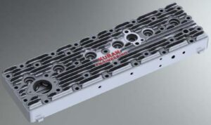
Figure 1 is a rendering of the Solidworks model. The model was sent to a company called ExOne for casting. They 3D printed the mold components.
Here is a link that shows their fluid flow and solidification modeling process and here is a link to the cylinder head casting process.
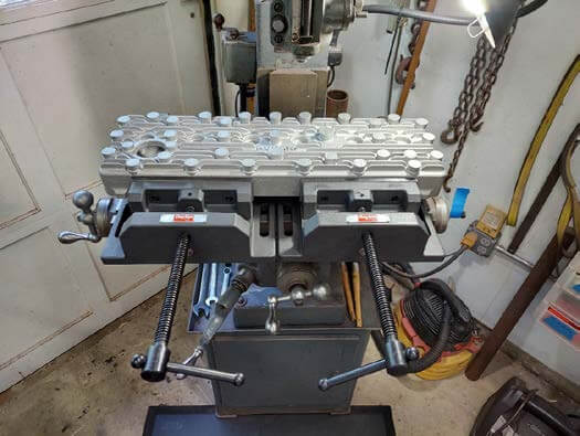
Figure 2 shows the casting on the Clausing 8520 milling machine, as it looked when I received it from ExOne.
Due to the mill’s limited travel in the x-y directions, it required four setups to reach all the features.
In this first operation, the 33 stud bosses, thermostat housing, distributor adapter, and the heater coolant boss were milled to the required height.
The next operation was to drill the stud holes, spark plug holes, etc., and cut threads where required.
The challenge was to locate the centers.
I decided to use the center stud hole, just above the “KURAN ENGINEERING” text as the x-y zero.
Where possible, I 3D printed alignment fixtures to help with hole locations (Figures 4 and 5 show two of them.)
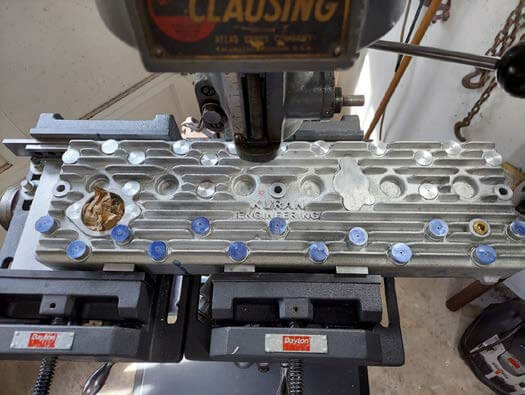
Figure 3 shows the passenger side stud bosses milled to height and three stud holes drilled.
The center stud hole center was located with a fixture but the front and back hole was located using the traverse handles.
Those two-hole centers are accurately located but so time-consuming that I decided to find a faster means to locate the centers. Since the copper head gasket was made from the model, I used it as a template to locate the stud holes.
To mill the remaining 13 stud bosses the head had to be unclamped and rotated 180 degrees, then moved again in the y-direction.
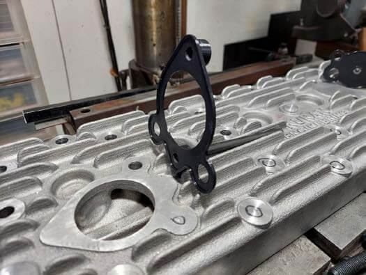
Figure 4 shows the 3D printed fixture used to locate the distributor drive shaft hole and the adapter stud hole.
The fixture snaps onto/over the 1/16” high distributor boss.
The two existing holes are stud holes and were located by a separate process.
Using the fixture ensured that the distributor driveshaft hole and the adapter are concentric.
Their location, relative to the two stud holes, is not as critical as the stud-to-stud hole locations.
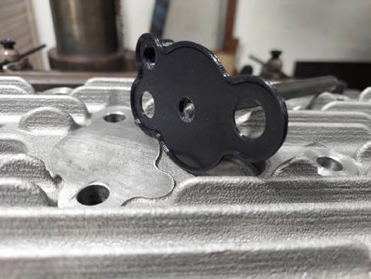
Figure 5 shows the 3D printed fixture for locating the thermostat housing mounting holes.
Once snapped into place a transfer punch was used to locate the centers.
The holes were drilled and tapped on a drill press.
The head was moved between the mill and the drill press several times.
This was new territory for me and I didn’t know, for sure, the best approach.
The one thing I did know for sure was that I did not want to drill a hole in the wrong place.
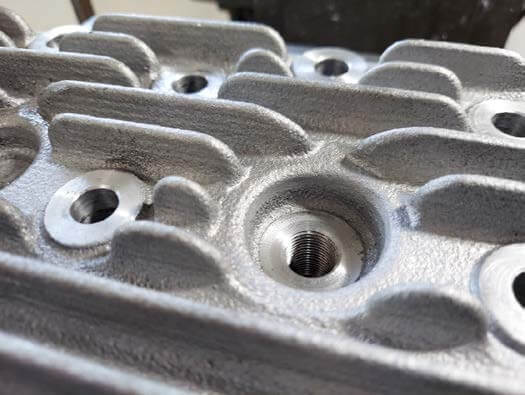
Figure 6 shows the first spark plug hole drilled, tapped, and spotfaced.
The hole center was located with a 3D-printed fixture.
The fixture, with a center hole for a transfer punch, was pressed into the plug recess.
This spark plug operation was done on the milling machine.
A hole was drilled for the spotface pilot, spotfaced to a depth of 1/32 inch, drilled again to the 14 x 1.25 mm tap drill size then tapped.
All six plug spotfaces would need to be recut after the combustion chambers were finished machined to get the spark plug electrode in the correct location with regard to depth.
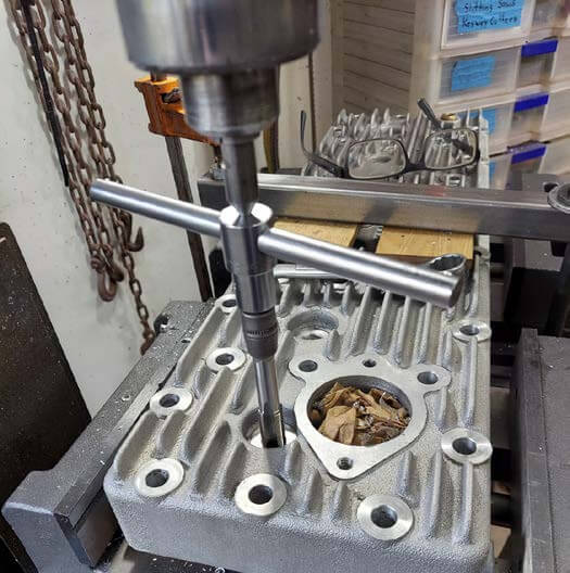
Figure 7 shows the spark plug hole tapping operation.
Using the setup shown ensured that the tap was perpendicular to the drilled hole.
I used the down-feed handle to apply a constant force to the tap.
To ensure that the first thread starts to cut properly, I tied a 5-pound weight to a cord that is attached to the down-feed handle.
With the weight attached, the downforce is applied automatically and consistently.
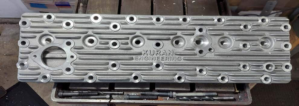
Figure 8 shows the top of the cylinder head with all the features machined. To machine the sides, the two 8” machinist vices were moved from the mill to the drill press.
The head was clamped on its side for drilling and tapping.
The passenger side has two 3/8” NPT threaded holes for the coolant bypass tube.
The driver side has two NPT threaded holes for the coolant sensors (one for the ECU and one for the OEM cluster gauge).
On the driver side there are two 3/8 – 16 threaded holes for the oil canister mount and two 5/16 – 16 threaded holes for the throttle linkage mount.
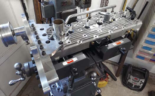
Figure 9 shows the head with everything, except the throttle linkage bracket, attached to it.
Here is a short video that shows the head from a different perspective.
To provide additional machining allowance, 1/8” of material was added to the model’s bottom deck and combustion chambers.
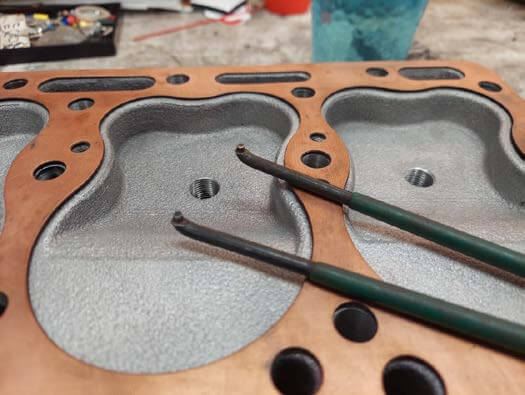
Figure 10 shows how the head gasket is used to highlight the added material.
The original plan was to work with a CNC shop to do the machine work, particularly the combustion chambers.
After two months of getting nowhere, I decided to buy a small three-axis milling machine and do the work myself.
Buying and setting up the machine was the easy part. Learning how to use it took some practice.
After setting up the toolpaths, I practiced with a piece of aluminum stock, machining every feature needed on the casting.
I had no experience with high-speed machining so turning endmills at 16000 to 18000 rpm was exciting, to say the least.
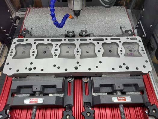
Figure 11 shows the bottom deck milled to get the required head thickness of 1.953” as measured from the bottom deck to the top of the stud bosses.
This dimension was important because the supercharger mount uses the front five stud bosses as its attachment point.
I did not want to modify or remake any of the components that were attached to the cylinder head.
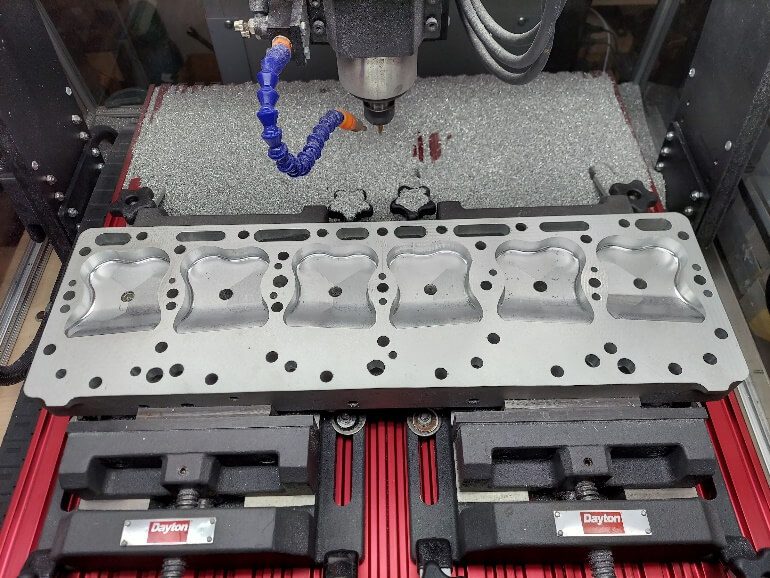
Figure 12 shows the finished combustion chambers. They are 100cc and when installed with an 8mm (0.031”) thick head gasket give a static compression ratio of 7.5:1 and a quench height of 0.041 inch.
With the head gasket installed, the chamber roof is 0.692” above the block deck.
Valve lift is 0.424 inch. There is 0.125” clearance around the backside of the valves. I don’t know if that is enough to be considered unshrouded.
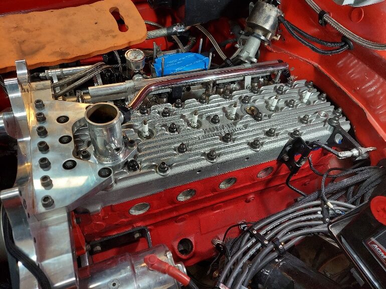
Figure 13 shows the finished combustion chamber depths, 0.661 was the dimension with a tolerance of plus 0.000”, minus 0.002 inch.
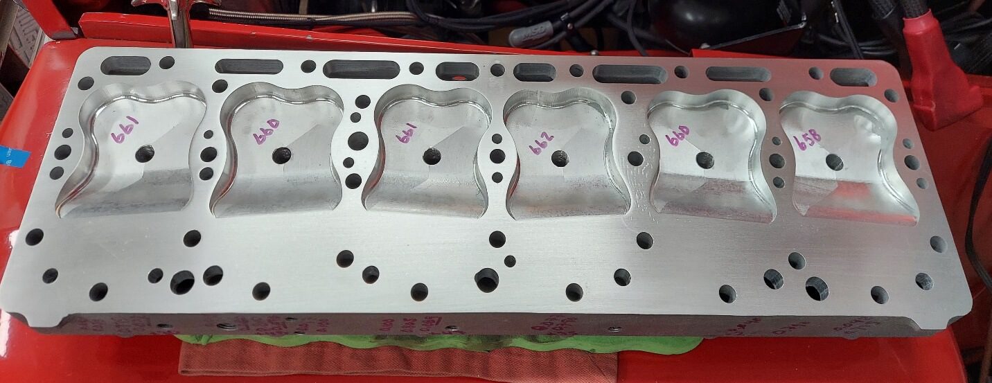
Figure 14 shows the cylinder head installed. Since it easily slid over the 33 head studs, I was finally assured that the 33 stud holes were located correctly.
The photo also shows that all 32 coolant passages were finished milled.
At this point I had become confident in setting up tool paths and ensuring the feature would be milled where it was supposed to be.
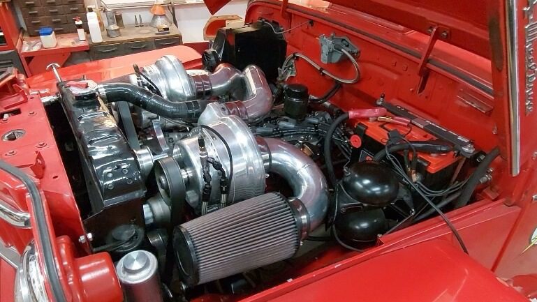
Figure 15 shows the engine ready for its first startup with the new cylinder head. Here is a short video that shows the engine running for the first time with the new head.