Getting Started
Although familiar with basic wiring concepts, I had almost no experience with audio, visual, fiber optic, printed circuits and control systems. I soon realized that hiring someone was not a realistic approach, so I needed to learn how to install and test the new systems. During the two years it took to wire the vehicle, much time spent learning now to do it. I spoke to electrical and electronic technicians, read articles, studied books and took online classes. I learned how to program micro controllers, such as the Arduino and Raspberry Pi, use an oscilloscope, assemble cable connectors and, perhaps most significantly, the importance of making good grounds.
Knowing how to build a system was important but knowing how to troubleshoot and fix problems that may arise later was equally important. Therefore, wiring diagrams were made at the system and component levels. Some of the diagrams developed into system diagrams that include component part numbers, interfaces and operating characteristics.
My goal is to leave the reader with an understanding of the design, engineering and fabrication effort that went into this part of the project that consumed about 3,000 labor hours.
Installation & Documentation Requirements
Before modifying existing wiring or added new systems, I established the following installation and documentation requirements.
Installation
- Grounds – ensure properly sized return paths where ever necessary.
- Wire properly sized for circuit loads. Service application may require larger sized wires or specialized jacket material.
- Provide circuit protection (fuses).
- Use relays to reduce switch loads.
- Standardize the use of wire colors and
- Wire labels – develop wire labeling plan.
- Connectors – use standard wire connectors.
- Soldering – use solder connection where appropriate.
- Grommets – ensure wire protection when passing through body panels.
- Clamps – ensure wires are bundled and secured to prevent damage.
- References – use automotive wiring how-to references as necessary.
Documentation
- Clarity – ensure diagram is easy to follow and understand.
- Use standard symbology (SAE Standard J2221_201408; dtd 2014-08-19 – Standardized Symbols for Electrical Circuit Diagrams).
- Annotate wire size and color.
- List component attributes such as manufacturer, part number, voltage and current.
- Label diagram with a descriptive title.
- Accuracy – ensure diagram reflects actual installed arrangement.
Original Chassis Wire Diagram
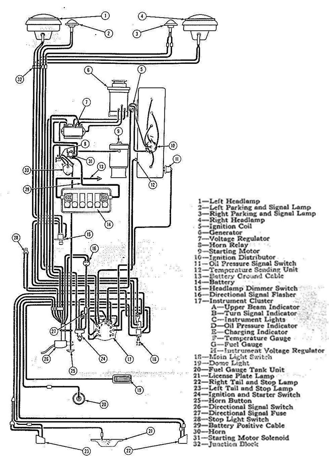
The OEM wiring diagram (Figure 1) included with the factory service manual is fairly simple; consisting of a single A-size sheet. It is accurate but its use of a single color and lack of detail make it difficult to follow. For example, it is easy to get confused when tracing wires associated with the instrument cluster and light switch.
The first step was to develop a single-sheet wire diagram, using the format shown in Figure 1. I enlarged the sheet size to 11” x 17” (B size) in order to add separation between the legacy components and to have space to add new components.
Modified Chassis Wire Diagram
The biggest change to the original chassis wire diagram was the installation of electronic ignition, fuel injection and the sensors associated with the Holley Dominator engine control unit. Other changes include installation of relays for the horn and light circuits, backup camera, PC & monitor, electric fuel pump, alternator, and the third brake light.
To provide the desired clarity, separate diagrams were created for each of the electrical sub-systems. The turn signals, ignition switch, light switch and instrument cluster are now shown with considerable detail.
Enhanced Vehicle Wire Diagram
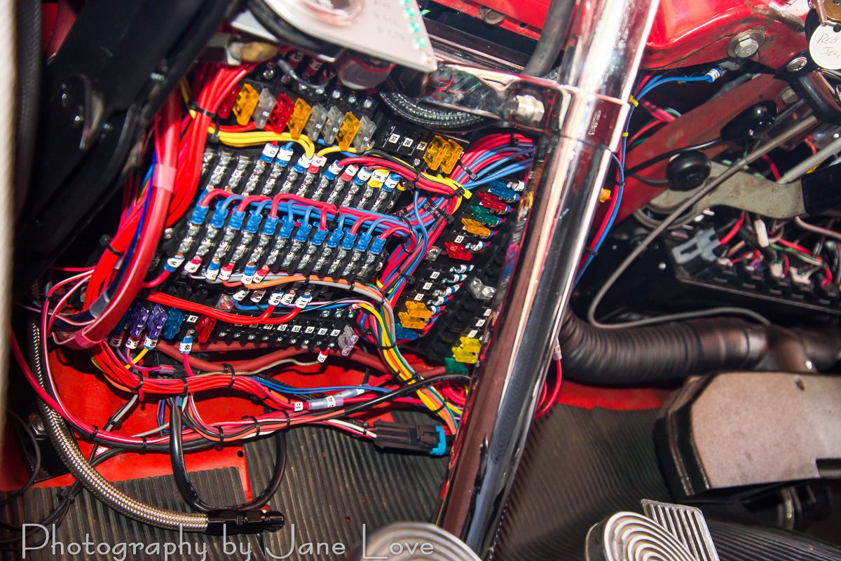
All circuits originate from the power center, shown in Figure 2. Each connector and terminal is label to ensure they are connected in the correct place. The labels are also seen on each wiring diagram.
You can read more about the wiring here and a related article that is specific to automotive connectors here.
WIRE DIAGRAMS
CLICK ON A TITLE TO VIEW THE SCHEMATIC
| Circuit Descriptions |
| Speedometer Electronic Cable Drive |
| Ignition Switch |
| Light Switch |
| Panel Heater |
| Power Generation & Distribution |
| Power Inverter |
| Horn |
| Dual Master Cylinder Data Display Rev (B) |
| Supercharger Oil Circulating Pump |
| Tachometer |
| USB Hub |
| Water Methanol Injection |
| CJ2A Wiring Diagram |
| PC & Audio |
| Fuel Pump & Injectors |