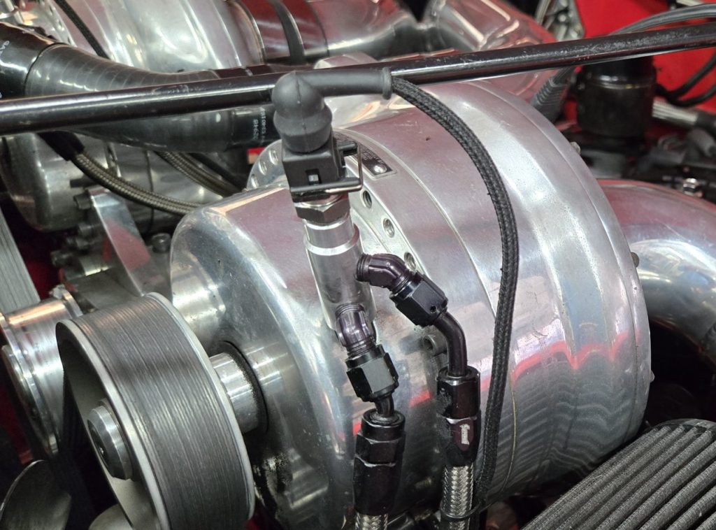
Supercharger Oil Cooling System
 December 19, 2024
Supercharger Oil Cooling System The report provides a comprehensive overview of the design, implementation, and testing of a supercharger oil cooling system tailored for Paxton SN60 and VS57 superchargers. These superchargers rely on a planetary ball drive mechanism, which is highly effective but prone to significant heat generation. Overheating risks are particularly acute during high-performance scenarios, such as sustained operation with boost levels exceeding 6 psi. This project was initiated to address these challenges, protect the hardware, and extend its service life by maintaining optimal oil temperatures. Background and Motivation Paxton SN60 and VS57 superchargers are valued for their performance...
Read More
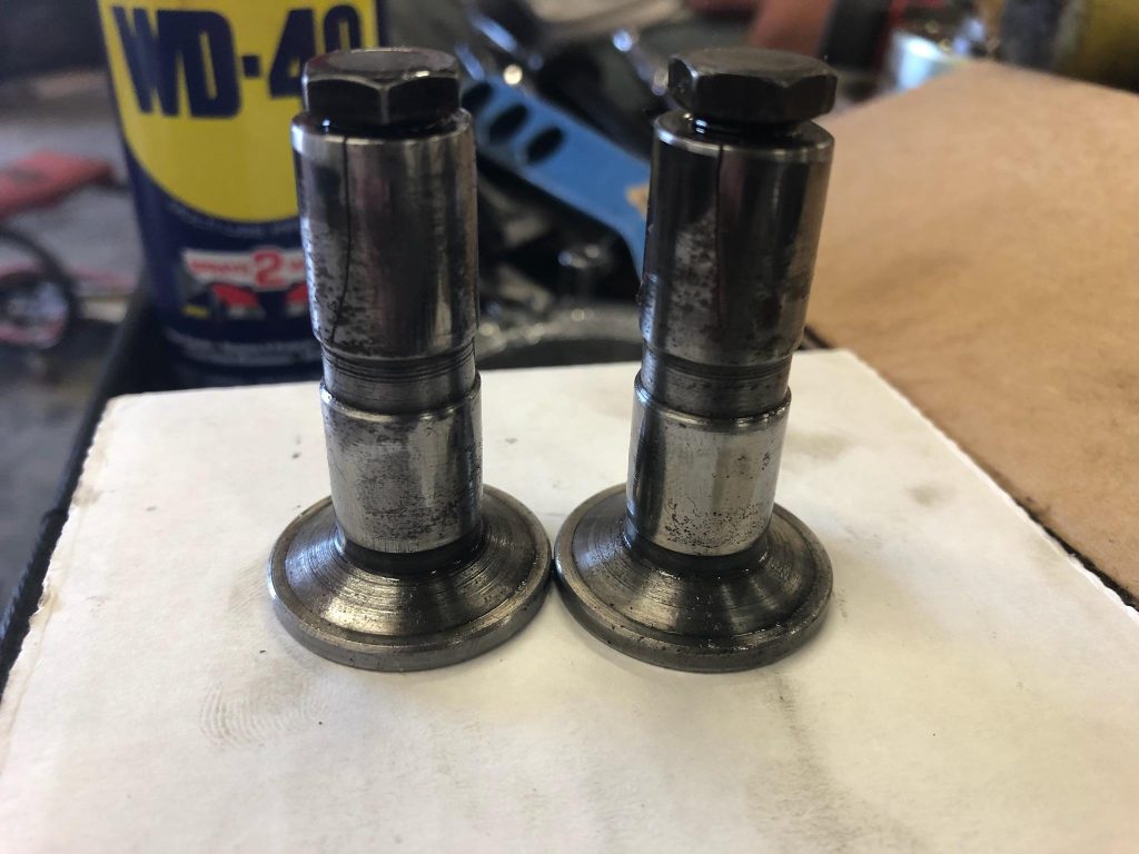
Tappet Replacement Project
December 14, 2024
Diagnosing and resolving a tappet failure in a modified engine can be a complex endeavor, especially when the problem leads to a complete redesign of the valvetrain. This project began with an abnormal exhaust gas temperature (EGT) reading in cylinder No. 2, which consistently displayed temperatures around 300°F, far below the 700–900°F range of the other cylinders. Adjustments to fuel and timing provided minimal improvement, prompting further investigation. A leak-down test revealed the intake valve was not sealing properly, leading to the discovery of tappet interference and, ultimately, cracked tappets. OEM Continental tappets were unsuitable due to their smaller face...
Read More
What Does It Do? A Reflection on the Purpose of Our Vehicles
December 8, 2024
We’ve all been there. You step outside and look at your vehicle—whether it’s a sleek sports car, a rugged Jeep, or a vintage muscle car—and feel a sense of pride. It’s polished, it’s clean, and it looks great sitting in your driveway. The paint gleams in the sunlight, the engine bay is spotless, and everything about it seems to say, “This is something special.” But then, a question pops into your head: What does it really do? At first, you might be caught off guard. After all, it’s a beautiful machine—what more does it need to do? It looks impressive,...
Read More
Crankcase Evacuation System (CES)
December 7, 2024
Overview The Crankcase Evacuation System (CES) was developed to address engine blow-by gases, which can cause crankcase overpressure, oil leaks, and decreased engine efficiency. Traditional systems, such as the Draft Tube and Positive Crankcase Ventilation (PCV) systems, have limitations for high-performance engines. This project explores mechanical and electrical CES configurations to maintain a crankcase vacuum of 5 in·Hg at 10 CFM flow, ensuring optimal engine performance and environmental compliance. Traditional Systems and Limitations Draft Tube System: Uses Bernoulli’s principle to create a low-pressure zone for ventilation but is ineffective at low speeds. Provides negligible crankcase vacuum at typical operating conditions....
Read More
Throttle Response Optimization – Part 1 of 3
November 22, 2024
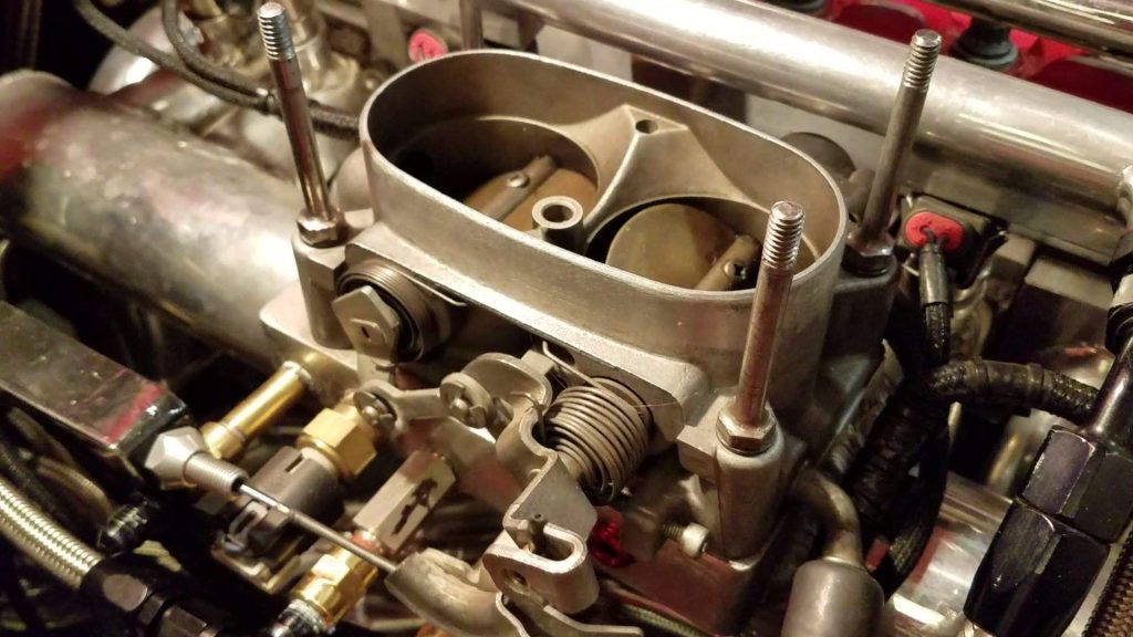
Part 1: The Dynamics of Throttle Plate Position and Flow Area Understanding the relationship between throttle plate position and airflow is critical for optimizing engine performance. This connection directly impacts how efficiently an engine can transition from idle to full throttle. In this post, we’ll break down this relationship and its significance. Figure 1 shows how the flow area changes with throttle plate position. The red curve represents the actual airflow through the throttle body, while the black line shows the output of a linear potentiometer directly linked to the throttle shaft. Key observations include: Nonlinearity in Low Throttle Positions:**...
Read More
Throttle Response Optimazation – Part 2 of 3
November 22, 2024
Part 2: Linear vs. Nonlinear Throttle Position Sensor Response Throttle control becomes a challenge when the engine demands rapid response, and the linear TPS struggles to keep up. This post examines why linear potentiometers fall short and how adjusting their response curve can provide a solution. Figure 2 highlights the mismatch between a linear TPS response and actual airflow requirements. The black line represents a direct 1:1 coupling between the TPS and the throttle shaft. The green curve, however, shows the desired convex response that aligns with engine needs. Key insights include: Mismatch in Early Throttle Movement:** The green curve...
Read More
Throttle Response Optimization – Part 3 of 3
November 22, 2024
Part 3: Mechanical and Electronic Solutions for Optimal Throttle Response To solve the enrichment problem, engineers can turn to either mechanical linkages or electronic modifications. This post explores both approaches and their advantages. Figure 3 shows how varying linkage ratios can create the desired convex response. By using levers, bellcranks, or idler shafts, engineers can: Accelerate TPS movement by linking a longer input arm to a shorter output arm generates a faster TPS response at low throttle positions. Align full throttle positions so that the TPS and throttle plate each reachs 100% open simultaneously, ensuring proper calibration. Instead of mechanical...
Read More
Cylinder Head Replacement Project – Machining
December 10, 2021
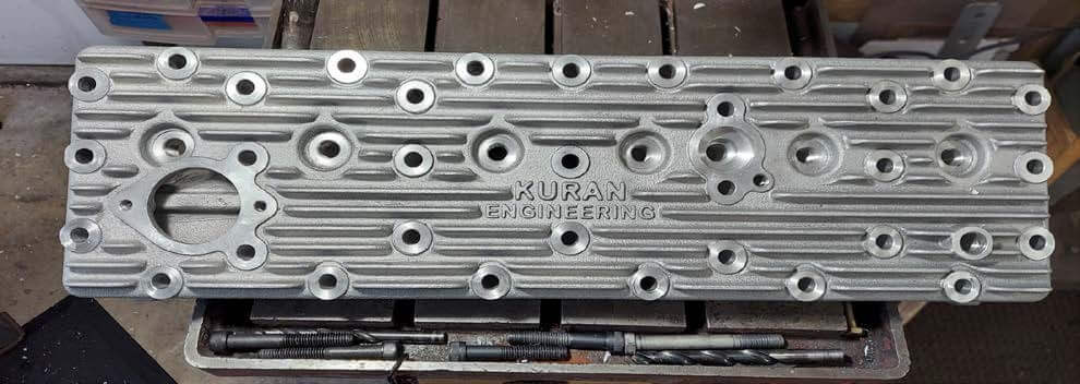
Cylinder Head Replacement Project - Machining This is a summary of the 13-month project to replace the damaged and unrepairable Edmunds aluminum cylinders on my 1960 Willys Super Hurricane engine. For more details about the project, visit my build thread, 1960 Willys Utility Wagon – Be Careful of Big Ideas on the Old Willys Forum. Figure 1 is a rendering of the Solidworks model. The model was sent to a company called ExOne for casting. They 3D printed the mold components. Here is a link that shows their fluid flow and solidification modeling process and here is a link to...
Read More

1960 Willys Utility Wagon – An Observation
December 28, 2020
When I am out and about with my 1960 Willys Utility Wagon, it is not unusual for people to ask “What is that?” or make the comment “I have never seen one of those.” The question I then ask myself is “Why don’t people know about Willys Utility Wagons?” If I were driving a 1969 Camaro most people would identify it, or at least recognize it as a ‘60s muscle car. So, what is the issue with Willys wagons? Uniqueness The Willys Utility Wagon’s versatility and capability were unique for that era. I am not aware of any other US...
Read More

Willys Utility Wagon – Unique, Rare, Collectible, or Simply Unremarkable
August 2, 2020
My Experience When I'm out and about with my 1960 Willys Utility Wagon, it is not unusual for people to ask “What is that?” or make the comment “I've never seen one of those.” I then ask myself “Why don’t people know about Willys Utility Wagons?” If I were driving a 1969 Camaro most people would identify it as a Chevrolet, or at least recognize it as a ‘60s muscle car. So, what is the issue with Willys wagons? Uniqueness The Willys Utility Wagon’s versatility and capability were unique for that era. I'm not aware of any other US auto...
Read More
What Would it Take to Keep Your Original Engine
July 19, 2020
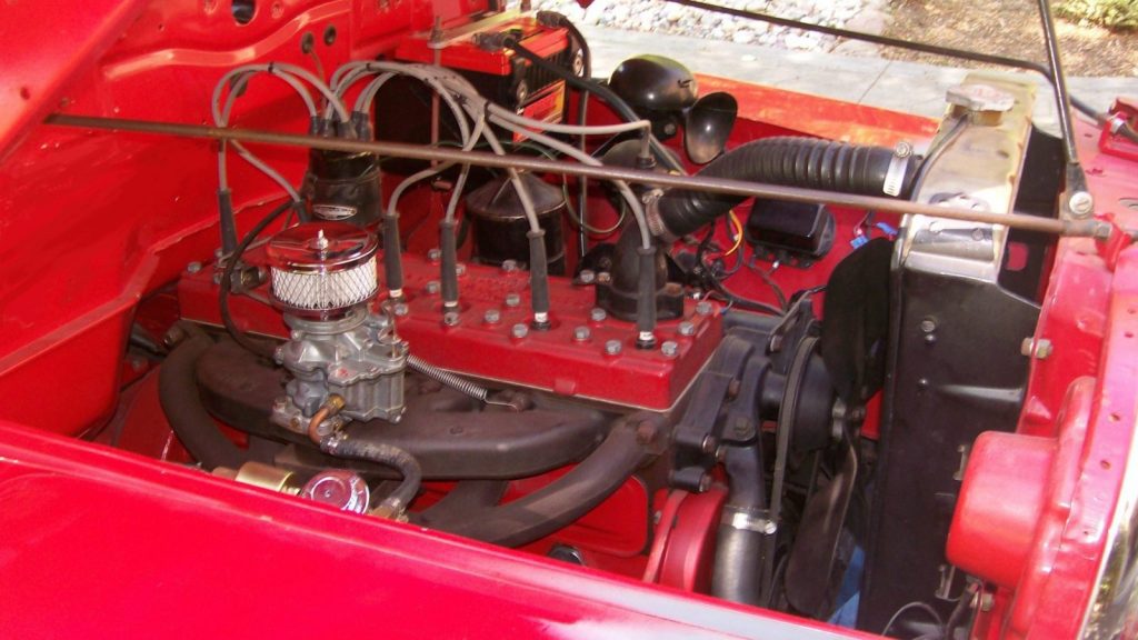
It Does Not Make Enough Power Recently, I overheard someone asking a question about replacing the F4-134 in his 1952 pickup. I began to wonder what it would take for most of us to leave the stock engine in place. The usual reason that I hear when asking why the engine was replaced is that it did not have enough power. I agree that the L4-134 Go Devil, L6-148 Lightning, F4-134 Hurricane, L6-161 Lightning, F6-161 Hurricane, L6-226 Super Hurricane or the 6-230 Tornado are not high performance engines, or even considered to be of moderate performance. Engine Performance Specifications My...
Read More
Ross TL-12 Steering Gear
July 19, 2020
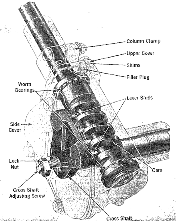
Ross TL-12 Steering Gear Pitman Arm to Sector Shaft Installation and Development of Assembly Specifications VEHICLE: 1960 WILLYS UTILITY WAGON SN: 54168 50039 Abstract The pitman arm to sector shaft fit is not usually checked before the steering gear is installed in the vehicle. Out of tolerance parts will not be noticed until it is time to install the pitman arm on the sector shaft. Since design dimensional data is not available, an alternative method must be used to identify out of tolerance features. This paper presents a method to visually...
Read More

Definition of an Original or Stock Vehicle
July 16, 2020
Making the decision to improve the looks and performance of my Willys was easy; deciding how to do it was the hard part. My first thoughts were to restore the vehicle but I realized that I didn't really understand what that meant. I realized that I had just encountered my first problem; the need to figure out what it was that I was trying to do with my vehicle. Was it a restoration? Was I fixing it up? Or was I modifying the vehicle? Certainly there is no lack of debate on this topic. To put the issue to rest,...
Read More
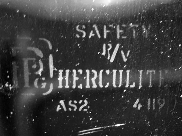
WINDOW GLASS REPLACEMENT CONSIDERATIONS FOR 1960 WILLYS UTILITY WAGON
November 1, 2016
THE USUAL SUPPLIERS My project was ready for window glass so I went to a couple of the usual sources; Walck’s 4 Wheel Drive and Kaiser Willys Auto Supply, INC to compare prices. The cost difference to purchase the necessary 14 windows individually was less than three percent, with Walck’s being the less expensive. Each supplier offers a kit that includes the 14-piece glass set for considerably less cost. However, Walck’s kit cost is about 12% less that the KW kit. OTHER CHOICES Before ordering I decided to look into a couple of the many alternative window glass sources. By chance...
Read More