
Ross TL-12 Steering Gear Pitman Arm to Sector Shaft Installation
and
Development of Assembly Specifications
VEHICLE: 1960 WILLYS UTILITY WAGON
SN: 54168 50039
Contents
Abstract
The pitman arm to sector shaft fit is not usually checked before the steering gear is installed in the vehicle. Out of tolerance parts will not be noticed until it is time to install the pitman arm on the sector shaft. Since design dimensional data is not available, an alternative method must be used to identify out of tolerance features. This paper presents a method to visually identify part deficiencies and to hand-fit out of tolerance parts.
The factory service manual does not specify the effective spline engagement length or the retaining nut tightening torque. Therefore, empirical evidence was used to develop pitman arm to sector shaft assembly specifications.
Introduction
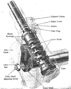
The Ross TL-12 (Willys PN: 810999) steering gear (Figure 1) was rebuilt to factory specifications. The rebuild included using a NOS (New Old Stock) sector shaft (Ross PN: TL124989) and NOS pitman arm (Willys PN: 810991).
While installing the pitman arm on the sector shaft, it became apparent that the NOS parts fit differently than the original parts. The Pitman arm did not slide onto the tapered spline as far as the original parts.
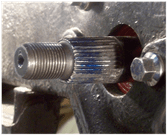
Figure 2 shows the original part Assembly with 1/8″ off-set gap between pitman arm face and edge of sector shaft spline.
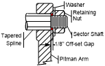
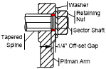
Figure 3 – NOS Part Assembly with 1/4″ off-set gap Between Pitman Arm Face and Edge of Sector Shaft Spline
Figure 3 shows the NOS part spline engagement and 1/4” gap between the pitman arm face and the splined section of the sector shaft. An obstruction prevented the NOS pitman arm from advancing onto the splined section an additional 1/8” to achieve the same spline engagement as the original parts. The 1/8” less spline engagement between the sector shaft and pitman arm results in about 14% less load-carrying capacity.
The pitman arm changes the rotary motion of the sector shaft to linear motion needed tosteer the wheels. The rotary to linear motion is transferred through an interference fit, tapered spline connection that has two load-carrying elements. One is the taper frictional force and the other is the spline shear stress. Correct dimensional tolerance is essential to achieve the design load-carrying capacity. The assembled splines should have nearly 100% surface area contact. If not, the maximum shear force will be reduced proportionally.
Advancement of the pitman arm onto the tapered spline must be far enough to exert the desired clamping force but not so far as to over-stress the hub, which may result in a cracking failure. It is beyond the scope of this paper to calculate spline shear stress and interference fit force.
Investigation
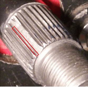
Visual Inspection – The pitman arm’s internal spline and the sector shaft’s external spline have 36 splines with one removed, or skipped, at each quadrant, creating a blind spline. The blind spline simplifies pitman arm installation since the arm has only four possible orientations, rather than thirty-six.
- Pitman Arm – Visual inspection revealed no obvious defects with the NOS pitman arm’s internal spline.
- Sector Shaft – Figure 4 shows incomplete removal of one of four blind splines. Incomplete machining caused interference with the pitman arm hub. The other three blind splines had the same defect. The remaining 32 splines are in good condition.
Dimensional Inspection – Without part design data, it was not possible to determine whether individual spline height, width, and base circle of the hub and shaft were within design tolerances. Measuring depth and width proved difficult and yielded unreliable results. However, measurement of the spline diameter showed the NOS shaft spline diameter to be about 0.020” larger than the original part. This larger diameter could be the cause of less spline engagement.
Spline Contact Area –Applying Prussian Blue made it possible to observe the contact pattern when the parts were assembled then taken apart. With two sets of parts, there are four assembly combinations. Following is the procedure used to assess each combination:
1) Apply Prussian Blue to pitman arm internal splines
2) Place pitman arm on sector shaft
3) Install washer
4) Install retaining nut and torque to 10 lb-ft
5) Measure and record gap between the pitman arm face and the edge of the sector shaft spline
6) Incrementally increase tightening torque by 5 lb-ft (record gap each time) until reaching 130 lb-ft
7) Remove retaining nut and washer
8) Remove pitman arm
9) Assess contact pattern
Original Pitman Arm to Original Sector Shaft Fit-up
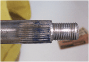
Figure 5 shows a near 100% contact pattern between the original pitman arm and the original sector shaft. There are some minor high and low spots, but the pattern is consistent all around the spline. The ending gap between the pitman arm face and the start of the sector shaft spline was one-eighth inch.
This pattern and off-set gap, demonstrated by the original parts, with 130 lb-ft of torque applied to the retaining nut, was set as the standard by which to judge the NOS part assembly.
NOS Pitman Arm to Original Sector Shaft Fit-up
When taken apart, the contact pattern was similar to Figure 5 and the gap between the Pitman arm face and the edge of the sector shaft spline was similar to the original part fit-up (1/8”) shown in Fig. 2. That observation led to the conclusion that the NOS pitman arm was dimensionally similar to the original pitman arm.
Original Pitman Arm to NOS Sector Shaft Fit-up
This configuration resulted in the contact pattern shown in Figure 6 with the 1/4″ gap shown in Figure 3, leading to the conclusion that the NOS sector shaft was dimensionally different from the original sector shaft. The visual inspection (Figure 4) that revealed incomplete machining of the external blind splines supports that conclusion. The contact pattern was noticeably visible on two sides, 180 degrees apart, indicating that the shaft spline area was somewhat oval-shaped. However, dimensional inspection did not reveal this condition.
NOS Pitman Arm to NOS Sector Shaft Fit-up
When taken apart, the contact pattern of this combination was similar to Figure 6 with the 1/4″ gap shown in Figure 3. This validated the previous conclusion that the NOS sector shaft spline dimensional variance was why the NOS to NOS fit-up was different than the original part fit-up.
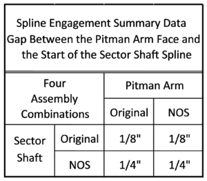
Figure 7 shows a summary of the four fit-up combinations. Only the two combinations that included the NOS sector shaft resulted in a 1/4″ gap between the pitman arm face and the edge of the sector shaft spline.
Pitman Arm Installation Specifications
The Jeep factory service manual describes the sequence of part assembly, specifies cam end play and sector shaft backlash, but it does not provide specifications for the pitman arm retaining nut tightening torque or minimum spline engagement. A 1953 edition of Motor’s Auto Repair Manual includes general assembly instructions similar to the Jeep service manual, but provides no specifications for pitman arm assembly.
The sector shaft tapered spline, combined with an interference fit achieved by the retaining nut force, holds the pitman arm in place. The sector shaft spline is about 1-1/2” long and the pitman arm spline is about 1” long. Therefore, the maximum spline engagement is about one-inch. At that point, the pitman arm front face would be flush with the edge of the sector shaft spline. There would be no gap as shown in Figures 2 and 3. A flush condition is not desirable since it would be impossible to know if the desired interference fit has been achieved. Therefore, a gap must remain between the parts, but it must be minimized since any remaining gap reduces spline engagement length.
The original parts provided a source from which to obtain reference data; specifically, how far the pitman arm engages the shaft at various retaining nut torque values. In order to check spline contact area, the pitman arm was placed on the sector shaft, the retaining nut tightened to 10 lb-ft, then the distance from the pitman arm front face to the edge of the sector shaft spline was measured and recorded. Tightening torque was then increased in 5 lb-ft increments, spline engagement measured, recorded, then repeated until 130 lb-ft was reached.
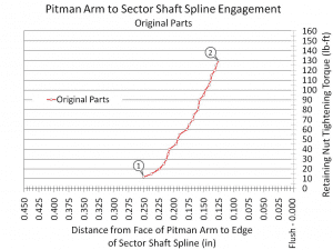
Figure 8 shows the progression of spline engagement as a function of retaining nut tightening torque. At the start (Point 1) the Pitman was 0.250″ from being flush with the edge of the sector shaft spline. At 130 lb-ft (Point 2) the remaining gap was 0.125 inch.
Although SAE torque tables recommend a tightening torque range of 238 to 357 lb-ft for 3/4-16 Grade 5 fasteners, continuing to increase the torque did not “feel” right. Therefore a practical retaining nut tightening torque range is 125 – 150 lb-ft.
Another attempt to validate spline engagement was made by obtaining in-service data from two other vehicles with the same steering gear. The owners of those vehicles were reluctant to remove and reinstall the pitman arm so additional tightening torque data was not obtained. However, the owners did take sector shaft to pitman reference measurements. Assuming a plus or minus 1/16” measurement error, those pitman arms each have about 7/8” spline engagement, or about 1/8” gap, similar to Figure 2, between the pitman arm face and the edge of the sector shaft spline. Therefore 1/16” to 1/8” gap between the pitman arm face and edge of the sector shaft seems a reasonable specification range.
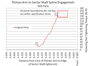
Figure 9 shows the gap and torque limits determined by using original part assembly data from Figure 8 and in-service reference data. The pitman arm to sector shaft assembly specification is:
Gap between the pitman arm face and edge of sector shaft: 0.062” – 0.125” with 125 – 150 lb-ft torque applied to the retaining nut. Graphite based anti-seize compound applied to sector shaft spline and threads. SAE 30 motor oil used as lubricant between nut and washer.
Solution
Figure 6 shows sector shaft high spots revealed by using the bluing procedure explained previously. A triangular hand scraper was used to remove small amounts of material from the blued areas.
Using a hand process ensured good control of themachining operation. Using a power tool,such
as a small die grinder, would have been much faster but could have easily resulted in a damaged part.
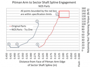
Figure 10 shows that at 10 lb-ft of torque the NOS pitman arm was 0.425” (Point 3) from full engagement versus 0.250” for the original parts. After repeating the blue-scrape procedure nine times, the face of the NOS pitman was 0.375” (Point 4) from the edge of the sector shaft spline.
Although the pitman arm was 0.125” farther out than the original parts at 10 lb-ft (Point 1), an assembly attempt was made. The linear progression from 10 lb-ft to 50 lb-ft was encouraging. However, at 100 lb-ft (Point 5) it became apparent that with almost 1/8” more engagement needed, full engagement would most likely not occur at 130 lb-ft.
Figure 11 shows that the next blue-scrape procedure started at Point 6 and repeated until spli ne engagement at 10 lb-ft was the same as for the original parts at 10 lb-ft (Point 1).
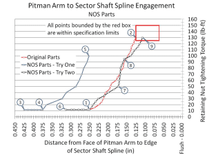
The progression of engagement verses applied torque continued to follow the pattern of the first try up to 50 lb-ft (Point 7). At that point, the torque increased with very little engagement increase (Point 8).
The nut was removed and lubricant applied between it and the washer to reduce friction. The lubricant resulted in a greater rate of engagement at each applied torque setting. At 130 lb-ft of torque, the NOS parts were engaged 0.018” further on the shaft than the original parts (Point 9) and within the specified limits.
Conclusion
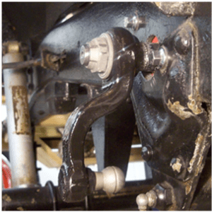
When the pitman arm to sector shaft spline engagement and retaining nut tightening torque falls within the specification limits shown in Fig. 10, an acceptable installation is achieved. Figure 12 shows an acceptable pitman arm installation on the subject vehicle.
Because the pitman arm to sector shaft connection is a steering system point of failure, adequate spline engagement and holding force is critical. Adherence to this specification will reduce the probability of a preventable failure.
Care must be taken to minimize the amount of material removed from the splines since their surfaces are hardened. Material removal did not exceed 0.010 inch. Surface hardness depth is estimated at 0.030 inch.
Ensure that the splines are clean and free of paint. Painted surfaces will prevent proper spline engagement.